|
|
|
|
|
|
|
|
|
|
|
|
| Ask the Experts | |||||||
|
|||||||
|
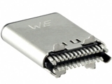
April 16, 2024 - Updated April 21, 2020 - Originally Posted Assembly Question for Soldering USB Connectors
What is the best way of mounting these on the edge of the board, ideally using an automated process? Only one side of the board is populated with SMT, is there a method to easily apply paste to the second side before mounting this connector? P.B. |
|||||||
| Expert Panel Responses | |||||||
|
For straddle mount connectors, SMT1 - print paste on the connector pads. No component placement. Reflow. You now have pretinned the pads and have solder bumps on the pads SMT2 - print paste on connector pads; assemble components. Reflow After fixing the straddle mount connector, hot bar solder the connector leads to the pretinned bumps; this step would be preceded by automated flux deposition (spray / pin transfer).
Technical Manager - Europe Indium Corp. Currently with Indium Corporation and responsible for technology programs and technical support for customers in Europe. Over 15 yrs experience in SMT, Power, Thermal & Semiconductor Applications. Masters Degree in Industrial Engg, State University of New York-Binghamton.
For this volume you may want to consider a selective solid solder deposit on the PWB. This is a process that applies and flattens solder to the pads and has a flux/adhesive applied over the solder. You could then clip the straddle mount device over the pads and reflow normally. I have seen this done selectively, where only certain pads have the solid solder deposit. You may want to recess the stencil over these areas to prevent interference with the paste application of all of the other components. Another method may be to put solder paste on the top side with the rest of the parts, install the part, and get the 2nd side with a selective solder machine.
PCBA Engineering Liaison General Atomics Electromagnetic Systems Group Kevin has over 30 years of experience in process and manufacturing engineering serving in both EMS and OEM companies. Expertise includes all aspects of SMT as well as wave solder and CCA materials such as PCBs, solder material, and component finishes. Kevin has developed processes for thousands of assemblies from stencil printing to conformal coating and testing.
You could screen paste and reflow the first side to form solder bumps on the pads. Apply liquid flux to the solder bumps prior to screening paste on the second side. Slide the straddle-mount components into place prior to automated placement of the second side parts. You may need some trial and error to develop second-side stencil apertures that will deposit enough solder, but not create solder bridges. I have had good results with using wedge-shaped apertures.
Principal Product Engineer Benchmark Electronics, Inc. 30+ years of experience working with electronic and electro-mechanical manufacturing and design (medical, automotive, military, computer, and industrial controls). Military veteran - served as a Combat Engineer with the United States Marine Corps.
First things first, the paste question. This is a 0.5mm pitch part, so it's not a really aggressive lead pitch, but small enough that using a non-stenciled approach to paste application is going to yield poor results due to shorting risk. I'd suggest that the most favorable approach would be to stencil paste on the side containing no other SMT first. Then, use a support with relief for the paste location when printing the SMT side of the board. Both sides will have to be printed and the board reflowed within a reasonable time, and this timeframe will depend on the specific paste used. Further, since this connector slides on, you'll have to accommodate for the connector pushing the paste deposit, which may require some creativity in the pad and paste design to avoid risk of shorting. As to component assembly, I'm sure there are automated solutions for edge assembly, but not sure that a volume of 50k/year justifies the investment. I'd suggest working with the manufacturer as they will be aware of what assembly solutions (manual and automated) are being used to mount their component.
Process Engineer Astronautics Fritz's career in electronics manufacturing has included diverse engineering roles including PWB fabrication, thick film print & fire, SMT and wave/selective solder process engineering, and electronics materials development and marketing. Fritz's educational background is in mechanical engineering with an emphasis on materials science. Design of Experiments (DoE) techniques have been an area of independent study. Fritz has published over a dozen papers at various industry conferences.
Straddle mount connectors are typically attached with reflow soldering after solder paste deposition by either stencil printing or solder paste dispensing. Since the solder paste needs to be deposited very close to the board edge, fixturing of the board is a critical issue. Dispensing is a more effective solution since paste deposition can be controlled much easier In terms of volume by means of tilting and rotating the dispensing nozzle. We also suggest contacting Nordson ASYMTEK since they have been producing automated jetting and fluid dispensing equipment for the electronics assembly since 1994.
General Manager Nordson SELECT Carlos Bouras is the General Manager of Nordson SELECT and has over 30 years of experience in the electronics manufacturing industry. Carlos's expertise is in process engineering, product development and manufacturing operations. For the past 15 years Carlos has focused specifically on automated assembly issues and is the holder of several US patents for non-contact dispensing and precision dispensing of adhesives for the packaging of microprocessor devices.
|
|||||||
| Submit A Comment | |||||||
|
Comments are reviewed prior to posting. You must include your full name to have your comments posted. We will not post your email address. |


|
Free Newsletter Subscription
Circuitnet is built for professionals who bear the responsibility of looking ahead, imagining the future, and preparing for it. Insert Your Email Address |
|
|
|
|
|
|
|
|