|
|
|
|
|
|
|
|
|
|
|
|
| Ask the Experts | ||||||||
|
||||||||
|
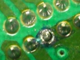
February 7, 2024 - Updated August 21, 2013 - Originally Posted What is Causing Solder Joint Cracking?
What might be the cause of the joint cracking? The connectors are soldered manually. Could selective soldering provide more consistent solder joints and thus reduce or eliminate the cracking? D.N. |
||||||||
| Expert Panel Responses | ||||||||
|
That solder joint appears to have been defective from the get-go. You probably had just a small whisker of solder making the connection and after a year of vibration in the dashboard, that whisker finally broke. This should have been caught during a visual inspection before the board left your assembly facility.
Senior Applications Engineer Flexible Circuit Technologies Mark Finstad has over 30 years in the flex circuit industry in both design and manufacturing. He is a regular speaker at IPC APEX (Professional development courses) and PCB West (flex circuit design courses). He is also vice chair of IPC-2223 and active member of IPC-6013. Finstad has extensive experience with both domestic and off-shore manufacturing.
Talking about a connector soldered to the board - this is the interface with other assemblies in the final product. So a cable or other assembly is connected to this. Vibrations can cause different issues on circuit board assembly including a fracture in solder joints. I would recommend to expand your investigation and work to collect more data - what is the assembly connected to and how are those sub-assemblies connected together and secured in the final assembly (top level). It looks to me that you've already pointed the root cause to the hand soldering process. For the specific soldering process - the selective soldering is for sure a lot more consistent than the hand soldering. You can control everything - dwell time,preheat time, flux quantity, temperature etc. The manual operation will introduce the human factor: not all the operators are using the tools the same way, feed the soldering wire at the same rate (maybe they do not even use the same solder wire diameter). Again, I strongly recommend further investigations - a cross section of the specific solder joints will tell you a story - is this solder related(voids in the solder joints, excessive temperature/thermal stress in the soldering process, insufficient solder, etc), is it mechanical stress or a combination of the two?
Engineering and Operations Management Independent Consultant Georgian Simion is an independent consultant with 20+ years in electronics manufacturing engineering and operations.
Contact me at georgiansimion@yahoo.com. Manual soldering has many variable associated with the process.Training is a must to reduce many of the variables and change bad habits which have evolved within the process. Selective soldering systems are more consistent in their application of flux, solder, dwell time at the solder joint and cool down rate, which in effect reduces and eliminates many variables and would be advantageous to the reliability of the product. What may be causing the problem is vibration on the product. I would also consider the harmonic frequencies of the radio sound wave, as this product was identified as being beneath the dashboard of the automobile. Secondly, thermal excursion due to being in the dash, with the change in heat from the cabin of the car to the cool down of the A/C may also have some impact on the reliability of the product.
Vice President, Technical Director EPTAC Corporation At EPTAC Corporation, Mr. Lambert oversees content of course offerings, IPC Certification programs and provides customers with expert consultation in electronics manufacturing, including RoHS/WEEE and lead free issues. Leo is also the IPC General Chairman for the Assembly/Joining Process Committee.
This sounds like intermittent cold solder joints. You should be able to get a more repeatable process from a selective solder process, although it needs to be set up correctly initially or you may end up with the same problems (some pins may require longer dwell times than others due to ground planes).
M.O.L.E. Line Product Manager Electronic Controls Design, Inc. (ECD) Mark Waterman is a trainer and field engineer with 17 years experience in service and applications specialties. Intimate knowledge of soldering processes and measurement systems. Six sigma and statistical process control generalist.
Although this may be caused by an actual soldering problem, I suspect it is a handling problem in your factory. The physical handling of PC board assemblies and storing them in a variety of holders can tend to bend or flex the PC board. This can cause microfractures in solder joints and board circuitry. The board will pass all the testing and burn-in, but then down the road months or years in the field vibration or screws holding the board in place can gradually degrade the micro fractures to crack and to finally fail. Take a walk through your factory and see what ways are being used that might be flexing the board.
President & CEO - Retired Bliss Industries, Inc. Retired - Mr. Bliss has 20+ years experience creating process methods that improve profitability by maximizing hidden unused capacity and throughput. Ken has expertise in all areas of manufacturing specializing in electronics assembly.
The failures in solder joints could be due to creep loading. Any mechanical low stress over a long duration leads to fractured joints. Check two things 1. Any mechanical tightening of the connector fixing screws post soldering which invariably adds to the creep loading. 2. Any unwanted mechanical stress during mating that would be stressing the solder joints.
Head-Quality Astra Microwave Products, Hyderabad, AP India Holds Degree in Engineering, started off as Scientist/Engineer in ISRO (Indian Space Research Organization) in Quality Assurance of Space hardware Electronics Production. Worked in the area of Parts, Material and Process; DPA, FA and Process Qualification for space and ground hardware. Later moved into Private sector and worked in the area of Quality Management Systems & ISO 9001 certification. Currently hold a position as Head-Quality in RF/Microwave Product manufacturing for Defense and Aerospace segment.
Reader Comment
Have you done a cross-section of the joint? What solder are you using? The joints look like they are not wetted at the shoulder of the hole wall. I suspect long soldering times with Pb-free solder have dissolved the copper at this location and resulted in a flimsy connection that failed with time.
Julie Silk, Agilent Technologies, USA
This can be difficult to see in visual inspection because the solder itself can coat over the lack of copper, but there is no robust connection. Selective soldering, with minimal solder contact time and a non-eroding alloy (i.e. SN100C), will be an improvement. There are many design and application variables that can cause the solder joint to fail in operation. From a soldering standpoint, you want to ensure that each pin has the same solder volume and achieve 100% barrel fill. Manual soldering with wire will not have this consistency. Without investing in a selective solder machine, you may want to look at flux-coated solder washer prefroms. The outer & inner diameters and thickness of the washer preform can be designed to achieve complete barrel fill. The washer is hand-placed and melted with a hot-air gun. The washer preform will give you the same volume of solder from pin to pin. The flux-coating on the washer takes away the step of adding flux separately.
Technical Manager - Europe Indium Corp. Currently with Indium Corporation and responsible for technology programs and technical support for customers in Europe. Over 15 yrs experience in SMT, Power, Thermal & Semiconductor Applications. Masters Degree in Industrial Engg, State University of New York-Binghamton.
Reader Comment
With the information available it is difficult to determine the root cause. Looking at the image and the data from your text I have three questions: is this an FR4 board, is the hole drilled or punched and is this a plated through hole?
Bob Rooks, TRAK Microwave
If the answer is: this is not an FR4board, the board holes are punched and hole is not a plated through hole. I would look at the board holes for debris from the punch process. It could be a worn or poor quality striper plate or prices. From the Picture it looks like there could be some blackening around the joint are you sure this hasn't Electromigrated and blown away by any chance. As there also appears to be solder on the resist next to it as well. Also if Single sided Boards well worth checking the registration of the hole to resist window and make sure they haven't been misregistered giving a very poor solderable finish on the Pad encouraging poor wetting (laminate ring inside the pad) which would offer poor mechanical strength. Selective soldering wouldn't make much difference.
Technical Sales Manager BLT Circuit Services Ltd Greg York has over thirty two years of service in Electronics industry. York has installed over 600 Lead Free Lines in Europe with Solder and flux systems as well as Technical Support on SMT lines and trouble shooting.
|
||||||||
| Submit A Comment | ||||||||
|
Comments are reviewed prior to posting. You must include your full name to have your comments posted. We will not post your email address. |


|
Free Newsletter Subscription
Circuitnet is built for professionals who bear the responsibility of looking ahead, imagining the future, and preparing for it. Insert Your Email Address |
|
|
|
|
|
|
|
|