|


|
|

| Ask the Experts | |||||||
|
|||||||
|
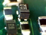
April 10, 2026 - Updated January 30, 2013 - Originally Posted Lifted Lead on SOT Component
What should we do in our process to eliminate this problem? R.D. |
|||||||
| Expert Panel Responses | |||||||
|
Excess solder deposition could be one potential cause for this issue. If there is excess solder on two of the three contact points, the excess could be causing the part to tilt back during reflow. You may want to compare the land pattern on the board, with the recommended pad layout from the component manufacturer, and rule out the possibility of a lead to pad compatibility issue.
Director Integrated Ideas & Technologies, Inc. Stephanie Nash is the Director of Technical Services & Marketing for Integrated Ideas & Technologies, Inc., a premier manufacturer of SMT stencils. She has been instrumental in the stencil design and technical support.
I would imagine it is the side with the single lead that is lifting up out of the solder or is not soldering. One of the reasons could be the solderability of the leads and the side with two leads gets heated and reflowed first and this physically pulls the component down, tilting it, so the single lead gets pulled up resulting in a tilted component and open solder joint.
Vice President, Technical Director EPTAC Corporation At EPTAC Corporation, Mr. Lambert oversees content of course offerings, IPC Certification programs and provides customers with expert consultation in electronics manufacturing, including RoHS/WEEE and lead free issues. Leo is also the IPC General Chairman for the Assembly/Joining Process Committee.
Assessing root cause on this defect is tricky. One or more of several possible causes may be in play. Let's imagine what is happening during assembly and reflow of the part. First, the paste is printed; we know there will be some volume variation, and this variation will be worse on the two small pads. The component terminations are only 0.010" x 0.006" on this part, so printing a small enough, repeatable enough paste volume is a major challenge.If one of the small apertures gets partially plugged, you can have insufficient paste volume. In addition, there may be too much volume from the larger aperture, which may cause problems during reflow. Once the board is printed, the part must be placed. Placement accuracy is critical, since the part is about the size of an 0402 chip, but the terminations are smaller. If the placement is off, there may be little or no contact between one or more part terminations and the paste. This may result in inadequate fluxing of that termination, and subsequent lack of wetting. After placement, successful reflow depends on both adequate fluxing of both the PWB lands and part terminations, and continued contact between PWB, solder and component during the heating transition through the liquidus temperature. If contact is not initiated or maintained, you will get an open joint. During melting of the solder, the part may tilt if there is too much solder on the larger aperture. Even if the smaller apertures were printed correctly, one of them may not be able to wet. If volume on one of the small terminations is low, the tendency to tilt may be worse, due to uneven forces. Part solderability may also play a role, but in this case I believe that careful optimization of the stencil apertures and paste printing process are what is required. In particular, pay attention to the volume of the large aperture being too great.
Process Engineer Astronautics Fritz's career in electronics manufacturing has included diverse engineering roles including PWB fabrication, thick film print & fire, SMT and wave/selective solder process engineering, and electronics materials development and marketing. Fritz's educational background is in mechanical engineering with an emphasis on materials science. Design of Experiments (DoE) techniques have been an area of independent study. Fritz has published over a dozen papers at various industry conferences.
From the image supplied, it appears the component lead did not "wet" (AKA: head in pillow) either because: the component lead was not solderable (oxide, contamination, etc); the paste flux was not aggressive or sufficient enough to break down the oxide; or the thermal profile was not of optimal time or temperature to allow proper "wetting." A thermal profile of the component's lead/pad can quickly confirm proper solder temperature and time. Too much Soak Time could destroy the flux before Liquidus. Then check the component's leads for solderability: do the look "clean" or are they discolored, etc. Finally is the solder paste applied of the required volume: not too much or too little for each pad.
Senior Project Engineer Electronic Controls Design Inc Paul has been with Electronic Controls Design Inc. (ECD) in Milwaukie, Oregon for over 45 years as a Senior Project Engineer. He has seen and worked with the electronic manufacturing industry from many points of view, including: technician, engineer, manufacture, and customer. His focus has been the design and application of measurement tools used to improve manufacturing thermal processes as well as moisture sensitive component storage solutions.
|
|||||||
| Submit A Comment | |||||||
|
Comments are reviewed prior to posting. You must include your full name to have your comments posted. We will not post your email address. |


|
Free Newsletter Subscription
Circuitnet is built for professionals who bear the responsibility of looking ahead, imagining the future, and preparing for it. Insert Your Email Address |
|


|