Stencil Printing for CSP's and 01005 Chips
Printing solder paste is a challenge when larger components are present. Paper explores solutions to solve this dilemma.
DOWNLOAD
Authored By:
William E. Coleman Ph.D.
Photo Stencil, Colorado Springs, CO USA
Chris Anglin
Indium, Clinton, NY USA
Summary
Printing solder paste for very small components like .3mm pitch CSP's and 01005 Chip Components is a challenge for the printing process when other larger components like RF shields, SMT Connectors, and large chip or resistor components are also present on the PCB. The smaller components require a stencil thickness typically of 3 mils (75u) to keep the Area Ratio greater than .55 for good paste transfer efficiency. The larger components require either more solder paste height or volume, thus a stencil thickness in the range of 4 to 5 mils (100 to 125u).
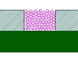
This paper will explore two stencil solutions to solve this dilemma. The first is a "Two Print Stencil" option where the small component apertures are printed with a thin stencil and the larger components with a thicker stencil with relief pockets for the first print. Successful prints with Keep-Outs as small as 15
mils (400u) will be demonstrated. The second solution is a stencil technology that will provide good past
e transfer efficiency for Area Ratio's be low .5. In this case a thicker stencil can be utilized to print all components. Paste transfer results for several different stencil types including Laser-Cut Fine Grain
stainless steel, Laser-Cut stainless steel with and w/o PTFE Teflon coating, AMTX E-FAB with and w/o PTFE coating for Area Ratios ranging from .4 up to .69.
Conclusions
Three different stencil options have been discussed to deal with the same challenge: inclusion of very small components with standard or large components in the same PCB. Step stencils have limitation when the small components are placed too close to the larger components. In this case there is insufficient keep-out area to allow squeegee blade access to the step down area. This is particularly a problem for the apertures positioned to the step walls oriented East or West to the squeegee stroke where the squeegee stroke is north to South.
Two Print Stencils have the disadvantage of requiring two in-line screen printers. However, there are also some advantages including different solder paste for the 1st and 2nd print. For example, a type 5 solder paste could be used for the 1st print and a type 3 solder paste for the 2nd print. Small keep-out areas are available with this stencil option. This paper reports keep-out areas as small as 15 mils (600u), which is normally suitable for most hand-held electronic devices.
The third stencil option to deal with this challenge is to improve the stencil print performance. The objective was to increase the performance to allow Area Ratio's less than .5 to be utilized. Several Stencil types were evaluated and compared. High magnification pictures revealed that the Electroform (E-FAB) stencil walls were the smoothest compared to Laser-cut stencils. Comparison of aperture clogging after printing was shown for Laser-cut and E-FAB stencils. Solder brick comparisons were also shown for the different stencil types.
The most important parameter (measurable) was the solder paste volume and solder paste volume variability. Several comparisons were made. The E-FAB stencil showed low variation and good volume down to an Area Ratio of .5, where the Laser-cut Datum FG stencil had major variability in the .5 and .6 Area Ratio region. In comparing DuraAlloy Laser-cut with Datum FG Laser-cut, the performance was similar, however DuraAlloy had lower variation in the .6 Area Ratio region. The comparison of E-FAB with and without PTFE coating was very interesting. Although the E-FAB stencil without PTFE coating showed slightly higher solder paste volume the variation of the E-FAB stencil with PTFE coating was less than the standard E-FAB stencil.
In fact the E-FAB stencil with PTFE coating had an average standard deviation of 5% at an Area Ratio of .44 while still yielding an average volume of 41% of theoretical volume. This is very encouraging and more work is planned to further develop PTFE coated E-FAB stencils.
Initially Published in the IPC Proceedings
|