|


|
|

Pin-in-Paste Calculations
Board Talk
TranscriptPhil Jim We are about to implement pin-in-paste technology. How can we insure proper plated hole fill during the screen printing process? Will the process require a different solder paste then the one we were using for SMT assemblies? So now our resident R.O.T. or reflow of through-hole expert, Phil Z. Phil I did a study of this many, many years ago back around very early '90s when I was at GSS/ARRAY. While I was doing my study at GSS/ARRAY Technologies, our good friend Joe Belmonte was hard at work doing the same thing at Motorola/Codex. And about that same time, I believe Bob Willis was also working on this process in his lab in an undisclosed location in England. Long story short, we all, independently came up with essentially the same methodology and similar formulas. Well, the idea of getting enough solder into the gap between the lead and the inside barrel of the hole was through over-printing. I think a lot of people freak out when they hear overprint because they think: "Oh man, whenever I have slight misprint of my solder I get solder balls". But this is the way to do it. Jim Phil Jim Phil Jim Phil One very important thing is that if you look at IPC-610 (Workmanship Standards), even going back to Rev C as well as Rev D, you'll find that it's not necessary to have a big positive fillet on both sides to comprise an acceptable through-hole solder joint. That big ol' positive-fillet-on-both-sides-of-the-PCB-joint is what we are used to with regard to wave and hand soldering. Reflow is a different animal. So even getting something that's actually flat with a surface, even slightly concave is usually more than enough strength - that joint is not going anywhere. Jim If you're interested more about the specifics of pin-in-paste or reflow of through-hole or intrusive soldering, send us a line. Comments
Jan 17, 2018
I think it will be a good idea to add solder thieve at the bottom side pad, so instead of dripping in the reflow, paste will go towards the thieve.
Mohammad Giyasuddin, Rauland-Borg Corporation
Feb 6, 2017
I have experienced this in a high volume automotive application. We worked with our paste supplier (Heraeus)on the flux chemistry to significantly reduce the problem.
Another issue is if the lead protrusion is too long (1.5mm+) the paste on the end of the lead will tend to drip off as the flux becomes active and the viscosity changes at the temperatures you mentioned. We tried to keep the lead protrusion to < 1.0mm.
Brian Chandler
Mar 3, 2010
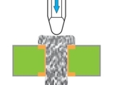
I have this USB 4-pin connectors using pin 'n paste process in one of our high runner boards. I just noticed it today (after 1200 boards) that the solder paste being pushed-out the 4 pins at the bottom side is dripping and accumulating inside the oven mostly on the 2nd to 3rd zone (temp is 120deg.c to 140 deg. c) of our 12-zone Vitronics oven.
Question is, is this normal? Or what is the normal inside the oven for pin n' paste process. The protrusion of the 4 pins at the bottom side is 1mm.
Rodolfo del Mundo
|
||||||||


|
Free Newsletter Subscription
Circuitnet is built for professionals who bear the responsibility of looking ahead, imagining the future, and preparing for it. Insert Your Email Address |
|


|